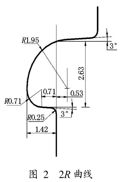
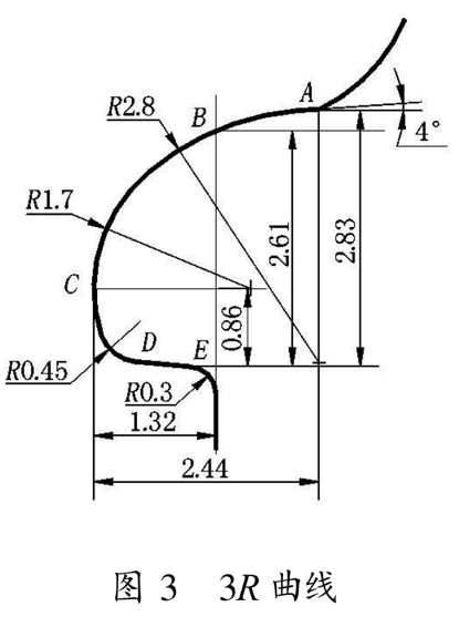
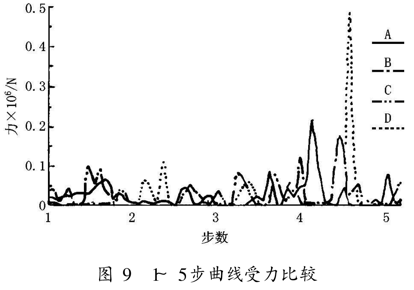
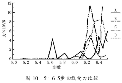
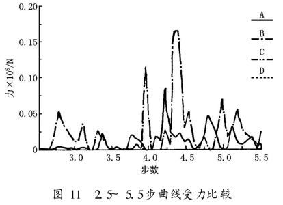
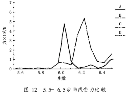
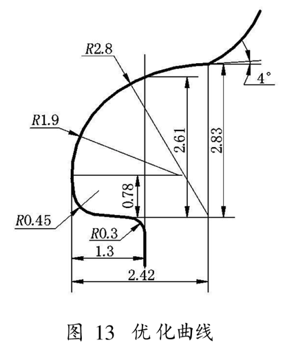
Analysis and Optimization of Double Rolling Head Rolling Roller Curve Text / Wang Wei ã€Abstract】The process of the encapsulation process was simulated by finite element simulation. The effect of each segment of the roller curve on the double beading was analyzed. The winding performance of the four curves was analyzed and compared, and the best performance was determined. The curve is encapsulated and optimized to obtain the desired envelope curve. [Keywords] double hemming; roll-up roller; groove curve; finite element analysis; curve optimization 0 Preface The sealing process of the tinplate three-piece can (or two-piece can) is done by the double crimping method. The double hemming method uses two roll-up rollers with different groove shapes, and the pre-flanged can body and the flange-shaped can lid are passed through the sequential two-feed motion at the joint of the can body and the can lid. The inner periphery is crimped, hooked, and pressed to achieve a sealing purpose. In the process of winding the head, the head roller is fed radially, and the periphery of the can is bent along the curve of the roller groove by means of the rotation of the can body, and the can body is hooked with the can body, so that the double crimping is basically formed. . The head winding roller is the basis of the entire curling. If the head curling is not up to the requirements, it is impossible to get a good curling result. Therefore, the groove curve of the head winding roller plays the double curling edge. Crucial role. The finite element method is a kind of calculation method which is produced with the rapid development and wide application of electronic computers. It is a numerical method that approximates the problem of general continuum. Through finite element analysis, parameter analysis and optimization of product mechanical structure performance can improve efficiency and accuracy, and reduce test cost. In fact, finite element analysis has become a numerical "virtual test" method to replace a large number of physical experiments. 1 finite element simulation Figure 1 is a model diagram of the finite element simulation simulation of the winding process. Since the winding curve and the edge curve of the can lid are composed of multiple tangential arcs and oblique lines, the structure is more complicated. Therefore, the model should be built in the modeling software and then imported into the finite element analysis software for analysis. . There are five sub-models in the figure: the left and right winding rollers, the upper pressing head, the can lid and the can body. The left and right rollers and the upper pressing head are rigid bodies, and the can lid and the can body are elastic bodies. During the sealing process, the can lid and the can body are rotated by the upper and lower trays. 2 The roller is fed radially and rotated under the action of friction. Under the action of the sealing force, the edge of the can lid gradually slides along the upper part of the curve of the groove of the roller to the bottom, and the edge of the can lid is bent and rotated inward by a curved molding to complete a sealing. 2 seal curve 2.1 Type of seal curve The roll-off roller must have a groove curve suitable for winding and easy to process in order to obtain a smooth, unnotched, airtight seal and smooth crimping, and improve the shelf quality of the can while maintaining the shelf life of the product. Can be extended. The shape and size of the groove curve of the sealing roller are related to the model of the sealing machine, the relative rotation of the roller and the tank, the thickness of the iron, the hardness and the diameter of the can, and are generally tangent to several arcs. Connected, the shape is generally similar, but its width, depth and arc radius are different. Figure 2 to Figure 5 are the 2R, 3R and 5R and Archimedes spiral roller curves. The rollers are used for the head winding of the tin can with a nominal diameter of Φ100 and a tinplate thickness of 0.25mm. In this paper, through the computer simulation, the model micro-element of Fig. 1 is taken, and the roller is also considered as the elastic body. The effect of each segment of the roller curve on the double-curling is analyzed, and the performance of the four curves is analyzed and compared. The curve is optimized. 2.2 The role of the various parts of the winding curve on the double crimping The different parts of the roller groove curve have different effects on the double crimping. Taking the 3R curve as an example, the AB segment in the figure guides the edge of the can lid, that is, guides the can lid into the roller groove to prepare for the double-sealing. The guiding line generally consists of a large radius arc and a diagonal line tangential to it, and the general inclination angle is T=1°~4°. The BC section is a double hemming auxiliary forming line. According to the force analysis, when the can lid slides on the curve above C, the bending force is larger and the friction is smaller, the can lid slides down quickly, and the edge of the can lid is between the can and the can body. The angle of the insertion becomes smaller, and the curvature of each part is almost constant, as shown in Fig. 7. The CD segment acts as a bending, so that the periphery of the can lid is bent and hooked to the can body, and the double crimping is basically formed. When the can lid slides on the curve of the CD segment, the bending force is the normal force and the friction force is increased, the sliding speed of the can lid is reduced, and the roller is continuously fed, which causes the can lid to bend inward under the molding action. As shown in Figure 8. The DE segment is the lead-out segment, which is a diagonal line with an inclination angle of U=1°~3°. The segment leads the front end of the can lid quickly, so that the angle between the edge of the can lid and the can body is further reduced, and the back of the can lid is attached to the roller. On the curve, a tighter seal is formed. 3 Results analysis The roller in the micro-model of Fig. 6 is replaced by the roller of the above four curves for finite element analysis, and the force distribution map of each roller in the bending process is obtained, as shown in Fig. 9 and Fig. 10, because the model only Take a micro-element, so the force value in the graph is smaller than the real value. There are 6.5 time steps in the winding process. Since the force of each roller suddenly increases in the 5.5~6.5 time step, 1 to 5.5, 5.5 to 6.5 are divided into 2 charts for analysis. In the figure, A, B, C and D represent 2R, 3R, 5R and Archimedes spiral rollers, respectively. It can be seen from Fig. 9 and Fig. 10 that although the Archimedes spiral roller has a small force during the winding process, it has stress concentration at the 2.5, 3.5, 4.5 and 6.5 time points, and the force is The value is larger than the other curves, which causes the roller to wear at the position of contact with the can lid at these four time points, which shortens the life of the roller. Considering that the Archimedes spiral is difficult to process, we first give up this. Kind of curve wheel. The 2R curve roller has a simple structure and can also complete the winding process, but it also has a pressure concentration phenomenon at the 4 and 5.6 time points, which indicates that the 2R curve with two curvatures cannot meet the sealing requirements. We compare the 3R and 5R curves: the 3R curve has a relatively smooth stress distribution throughout the winding process, and the 5R curve structure is not complicated enough to achieve the expected excellent effect, so the 3R3 curvature sealing curve can meet the sealing requirements. Moreover, considering the difficulty of processing, the 3R curve is the best performing sealing curve among the four curves. 4 Optimization of the envelope curve Among the four winding curves, the 3R curve is the most ideal roller groove curve, but in the 2.5 to 4.5 time period, the 3R curve still has stress concentration at 3, 4 and 4.5 time points, and at these 3 times. At the point, the stress distribution of the 5R curve is relatively smooth. In the 2.5~4.5 time period, the curve near the BC segment curve and the CD segment C point in the 3R curve participate in the volume sealing. We compare the 3R and 5R curves and find that near the C point, the radius of the 5R curve is R=2.182, R. The curve from =1.42 to R=0.9 is gradually changed, and the change is gentle, while the radius of the 3R curve is changed from R=2.8 to R=1.7. Replace R=1.7 with a curve of R=1.9, and tangential to the upper and lower curves, respectively, and then perform finite element analysis and compare with the 3R curve before the change. As shown in Fig. 11 and Fig. 12, where A is the changed curve and B is the curve before the change. It can be seen that several stress concentration phenomena of the previous 3R curve are eliminated or weakened after the change, so the optimized 3R curve is an ideal roller groove curve, as shown in FIG. After the groove curve is optimized, the stress distribution is uniform and the stress concentration is basically eliminated, so that the quality of the sealing can be improved, the defective rate is reduced, and the local wear of the roller is also avoided, thereby greatly improving the service life of the roller. Cpla Cutlery,Paper Straw,Disposable Cutlery Sets,Fork Cutlery Sets JIANGYIN BIOPACKAGE CO.,LTD , https://www.chinapulppackage.com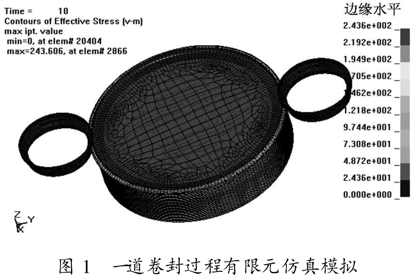
Although the four curves shown in FIGS. 2 to 5 are composed of different numbers of arcs, the width and depth of the curves are substantially the same. Each segment of the arc is tangentially connected, and the curvature gradually becomes larger to form a smooth curve, which achieves the requirements of small force and smooth curl, and can effectively avoid the stress concentration problem and make the stress distribution smoother. This can prevent the edge of the can lid from being bent and formed into a defective product, and can also reduce the wear of the roller, thereby extending the service life of the roller.