Design and Implementation of Vehicle Bootloader Based on CANFD Bus
As the market demands for car safety, intelligence, environmental protection, etc., the number of electronic control units for car assembly has increased rapidly. Therefore, automotive electronics puts higher demands on the bandwidth and transmission rate of the vehicle bus. At present, CAN (Controller Area Network) has been difficult to meet the increasing demand. CANFD (CAN with Flexible Data-Rate) optimizes the performance of the CAN bus in terms of both transmission rate and data length. This paper realizes the development of Bootloader software and hardware based on CANFD bus with speed of 5Mbps, which improves the downloading and updating rate of current automotive electronic controller software.
CANFD Introduction
The CANFD bus was first proposed by Bosch in 2011. In 2015, the International Organization for Standardization (ISO) officially released the 11188-1 protocol supporting CANFD. Compared with the CAN bus, CANFD mainly optimizes the following aspects:
• The arbitration field and the response field rate can be up to 1 Mbps; the data field rate is variable, and can reach 5 Mbps or higher according to the specific application scenario;
• The length of the data field is variable and the maximum data length is 64 bytes.
Combining the above optimizations, CANFD has advantages in the following aspects:
• Longer data fields and higher bandwidth utilization than traditional CAN;
• The transmission rate is faster. At present, the communication rate of 2Mbps can be achieved during normal communication. For example, replacing the original standard CAN network segment with the CANFD network segment can effectively reduce the load rate of the original network segment. When downloading, it can reach 5Mbps. Communication rate can effectively improve download efficiency;
• Can be used for transmission of signals longer than 8 bytes, such as PEPS identity authentication signal. In standard CAN, multiple CAN message transmissions are required. In CANFD, only one CANFD message is required.
The difference between CANFD message and CAN message format is shown in Figure 1.
• The FFD (FD format) bit has been added to the CANFD message to distinguish between traditional CAN messages and CANFD messages. The BRS (bit-rate switch) bit indicates the rate switching of the data field; the ESI (error state indicator) bit indicates the error definition state of the current node;
• Considering the increase in the length of the data field, in order to improve the reliability of communication, CANFD designed a new redundancy check mechanism;
• In addition to ISO11898, ISO15765-2 is also updated for CANFD applications. The transport layer of the current diagnostic protocol already supports the CANFD message format.
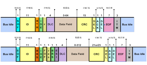
Figure 1. Comparison of CANFD message and CAN message format
Bootloader Design and Implementation • System Overview As shown in Figure 2, the complete refresh system mainly includes the Bootloader host computer, the flash writing tool and the controller that integrates the Bootloader lower computer software. The user sets the transmission rate, the request ID, and the like through the interactive interface of the upper computer and loads the controller software program that needs to be updated. The bootloader lower computer software receives the data transmitted by the host computer and writes it to the flash memory of the controller to realize online refresh of the controller. The brush writing tool is mainly used for CANFD message transmission.
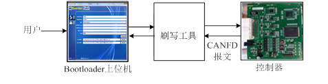
Figure 2. System structure diagram
• Hardware implementation In this experiment, a controller with a CANFD interface was developed. Figure 3 shows the hardware block diagram of the controller on the CANFD transceiver side. The system controller uses Renesas RH850 F1H series chip, the chip supports 6-channel CANFD, and the CANFD transceiver uses NXP's TJA1044GT. In order to ensure the EMC performance of the controller and the requirements of the network system, the transceiver needs to match the appropriate peripheral circuits, including the terminating resistor, the terminal capacitor and the common mode inductor.
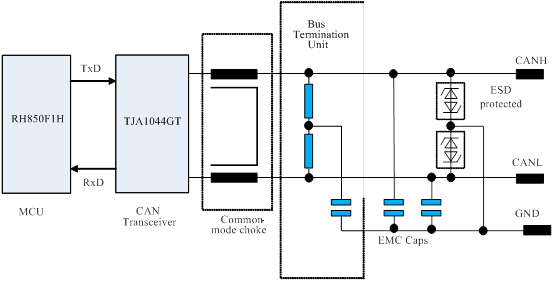
Figure 3. Schematic diagram of the RH850F1H CANFD transceiver
• Software implementation ♦ Bootloader lower computer software
Bootloader software is developed based on the HIS protocol. The Bootloader software architecture uses layered modules to minimize coupling between modules and improve development efficiency and quality.
The Bootloader software is mainly composed of CANFD Driver, CANFD TP and DCM. The CANFD Driver module implements CANFD controller and transceiver hardware initialization and CANFD message transmission and reception. CANFD TP mainly implements ISO 15765-2 protocol and diagnostic message processing. DCM The module implements the services related to program download in ISO 14229.
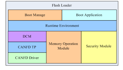
Figure 4. Bootloader software architecture
The Memory Operation Module is responsible for controller memory logic block configuration, segmentation processing, and non-volatile data management. The Security Module is responsible for secure access algorithms and data integrity algorithms. The Runtime Environment implements callback processing of the diagnostic protocol and controls the operation of the entire system. The upper layer of the Bootloader Manager is responsible for the application and bootloader startup processing and Stay In Boot function. The Bootloader Application implements clock configuration, time slice processing, and interrupt remapping.
♦ Bootloader PC software
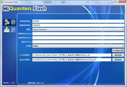
Figure 5. Bootloader host computer configuration interface
The main functions of the upper level are two parts: system setting and software upgrade. Arbitration field baud rate setting, data field baud rate setting, communication channel selection, request and response ID setting, and ID type selection can be performed in the system settings. In order to ensure the transmission data is valid, the upper computer is provided with the input of the CRC check algorithm and the secure access algorithm. The CRC check is used to ensure the integrity of the data transmission, and the secure access algorithm is consistent with the secure access algorithm in the lower computer. Software upgrades are primarily for driver file selection and the addition of data files that need to be refreshed.
ECU refresh experiment In order to verify the software refresh efficiency based on CANFD bus, eight sets of brush writing experiments were carried out based on the Bootloader software of CANFD bus and CAN bus respectively.
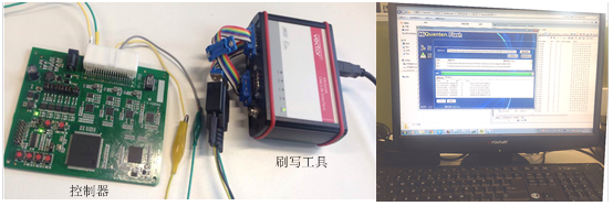
Figure 6. ECU software refresh experiment
Table 1. Comparison of brush write rates based on CANFD and CAN bus
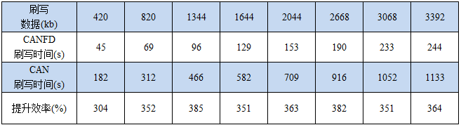
As shown in Table 1, the CANFD bus arbitration field is set at 500 kbps, the data field rate is set to 5 Mbps, and the CAN bus communication rate is set to 500 kbps. The data range from 420kb to 3392kb is compared with the experimental data. It can be seen that the CANFD-based brushing efficiency is maintained above 300% compared with the conventional CAN.
Summary This paper introduces the design and implementation of Bootloader software and hardware based on CANFD. It is verified by experiments that compared with the traditional CAN bus-based refresh mode, the refresh efficiency based on CANFD bus is greatly improved. At present, the in-vehicle network architecture is generally divided into multiple network segments according to the function of the controller, and each network segment exchanges information through the gateway. In the future vehicle controller refresh, the bandwidth of CANFD can be fully utilized to realize the simultaneous refresh of the multi-channel controller based on the gateway.

3 seater Fabric Sofa is a recliner sofa with 3 seats. It has two recliners at both sides. It's cover materials is fabric which is safe, environmentally friendly, comfortable cloth, made of wood frame and fine sponge, which brings people warm, comfortable and environmentally friendly family living environment.
You`ll feel very comfortable when you sit or recline on it for lunch break or after one day's work, and breathable performance of fabric sofa is good. The soft cloth is especially comfortable to touch, making people relax and feel the leisure.
3 seater fabric sofa is suitable for small space, it makes more sofa designs and colors than leather sofa, and it`s warm in winter, and breathable in summer, new fabric sofa won't give out a pungent leather smell at the same time.
3 seater fabric sofa gives a person a sense of leisure, and strong comfort, let a person have the feeling of relax when get home.
Grey Fabric Recliner Sofa,3 Seats Fabric Sofa,Fabric Recliner Sofas,I Shaped Fabric Sofa
Kaifeng Lanwei Smart Home Co., Ltd , https://www.sofawickles.com