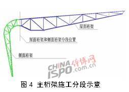
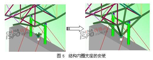
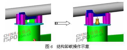
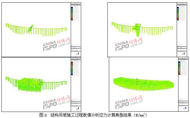
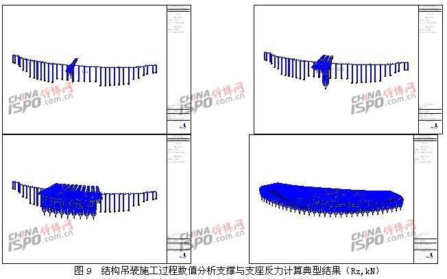
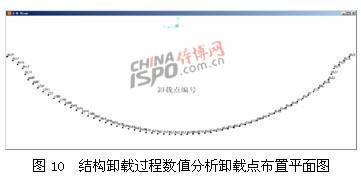
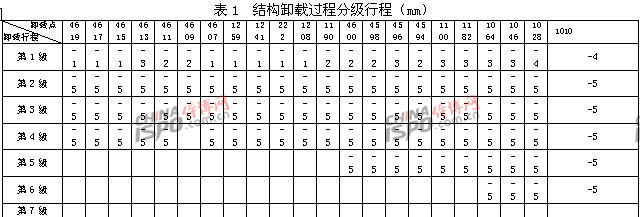
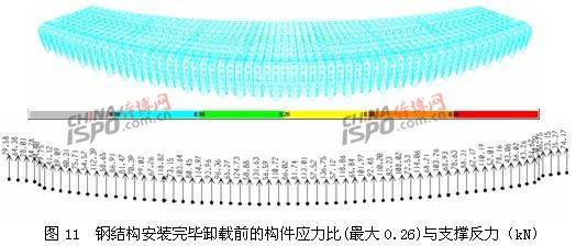
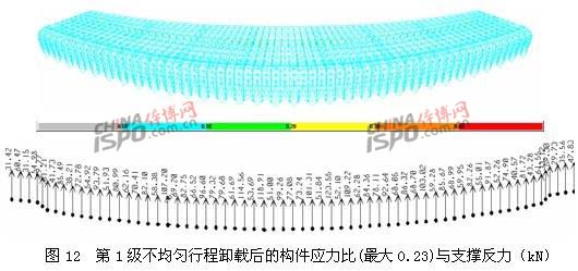
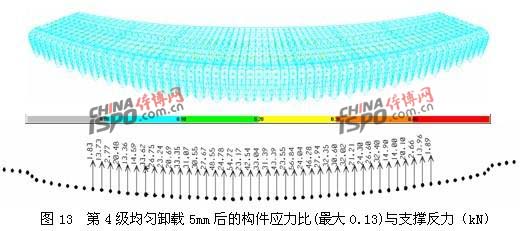
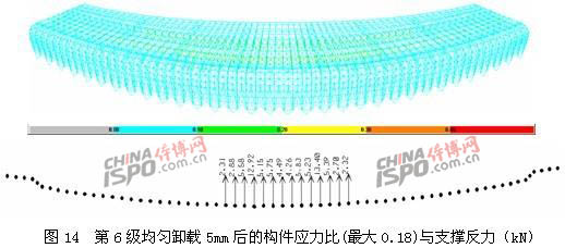
Introduce the production process and construction process of the steel structure of the main stadium of the Jinan Olympic Sports Center, the finite element numerical simulation analysis method of the steel structure construction process and the calculation results, and effectively guide the construction process of the steel structure. I. Project Overview The main stadium of Jinan Olympic Sports Center is located at Jingshi East Road, Longdong District, New City District, Jinan City. The overall building area is 154323m2 and can accommodate 60,000 seats. The roof of the stadium is similar in shape to Jinan City's “Liu Ye†shape, and the overall long axis of the elliptical plane is about 360m. The short axis is about 310m. The upper steel structure roof of the stadium adopts two independent folding plate-type space cantilevered truss shelter structures in the east and west. The maximum width of a monolithic shelter is about 70m, and the maximum length is about 330m in the north and south. The shelter is high in the middle and low on both sides with a height difference of 14m and the highest point is about 52m above the ground. The main cantilever has a maximum cantilever length of about 53m, a cantilever root maximum height of 7m, a minimum cantilever length of 28m, a cantilever root height of 5m, and a cantilever end height of 1.5m. The overall architectural effect of the structure is shown in Figure 1. The radial main trusses on each side of the east and west shelters of the steel structure roof of the stadium are 64 inches. The front roof of the canopy is a flat plate structure, and 9 rings of the secondary truss are arranged to form the main force system of the cantilever structure of the folding plate type space. . The middle truss lower chord plane is provided with six Φ50mm pre-stressed steel horizontal supports to enhance the overall lateral torsional stiffness of the structure, as shown in FIG. 2 . The 64-inch main truss is supported at the lower end by 32 Y-steel columns on the outer steel concrete piers, and the upper part (hanging roots) is supported by 32 node supports on the steel-concrete columns on the stands to form a stable spatial structure. Force system. The amount of steel structure used in the main stadium shelter is approximately 6600 t. It was produced and installed by Jiangsu Huning Steel Machine Co., Ltd. Second, steel structure production and construction 1. Characteristics of steel structure production and construction The construction and application of steel structures in this project mainly have the following characteristics: The main steel roof is double curved surface, with different elevations at various points and various spatial positioning points; the main structural members are overweight and long; the main truss span is large, the installation height is high, and the suspension The length of the pick is large; the nodes are symmetrical to the center line, but they are not exactly the same, especially for the cast steel nodes, the number of tire frames assembled on site is large. Among the difficulties in production and construction quality control are: control of the machining quality of steel components; measurement, pay-off and correction of structure installation site; on-site site layout; on-site installation of trusses; impact of high-altitude welding on installation quality; short installation period, safe construction Guarantee measures, etc. 2. Steel structure processing For the characteristics and difficulties of the processing and production of the structure of this project, a detailed welding process was prepared before the production. A series of technological measures were taken during the construction to ensure the quality of each component of the structure and thus ensure the quality requirements of the entire project. Due to the limited space and the emphasis of the explanation, only a brief introduction will be given here. The production of steel structural components and joints in this project can be divided into the following: production of steel pipe truss components, machining of node supports and production of cast steel nodes, and processing of secondary truss planes. For the tube truss, the intersecting welding nodes are mainly used, and some of the complex intersections of the upper and lower chords use cast steel processing nodes. (1) Fabrication of curved steel pipe truss structure The main specifications of this project intersecting line CNC cutting steel pipe are Φ127x6~Φ450x25. According to the actual conditions of manufacturing such structural components in factories, medium-frequency elbows are mainly used for steel pipes with smaller arcs, and cold-work elbows are used for components with larger arcs. The components are assembled and assembled in the factory, shipped to the site and assembled to form a body truss unit for lifting. (2) Manufacturing of bearing nodes The steel structure joints of this project mainly include steel pipe truss intersecting nodes, steel casting joints, prestressed steel bar joints, H-shaped steel column support joints, and steel pipe column support joints. The steel casting nodes adopt German standard DIN17182 and material grade GS-20Mn5V. For the important steel pipe column support nodes, the tooling measures of prefabricated plate-strength welding and installation of bulk butt welds in the installation are adopted. The typical structure of the inner ring bearing node production process is as follows (Figure 3): 1) Assemble the tire frame and tile the bottom plate; 2) Assembling the bottom plate of the bearing base and the stiffening plate of the bottom plate; 3) Assemble the bottom plate assembly of the bearing and the steel pipe column and refute and sculpt the upper component installation line; 4) Assembling the ribs of the upper member of the support; 5) Assembly of the support body and the main truss support member. 3. Steel structure construction process In combination with on-site civil construction conditions, the use of on-site, off-site partitioning, segmental structure assembly and lifting, acceptance and then step-by-step unloading, and ultimately complete the construction of the construction program. In the pre-construction completion pavilion, two temporary installations of internal and external construction shall be arranged to install the upper roof section truss, install the inner ring support, and then install the side section truss to complete the positioning welding of the outer ring support; The ring is mounted to the secondary truss and the main structure is fully hoisted. Afterwards, the inner ring temporary support frame was gradually removed (the outer ring support has been removed simultaneously while installing the inner ring support), and the structure was unloaded. (1) Main structure hoisting construction In the construction, the technical route of cranes symmetrically installed from the mid-axis of the site to the north-south symmetrical lifting and the installation of steel structures on both sides of the east and west canopies is divided into 8 hoisting areas symmetrically on both sides. The crawler cranes on the site and outside are selected to be 350t, 200t and 150t respectively. The main truss hoisting construction section is shown in Fig. 4. Each two trusses form a three-dimensional hoisting unit. The roof truss is lifted from the large crawler crane in the form of a three-dimensional segment. After the crane is in place, it is placed on a temporary support system to be fixed, adjusted, and mounted on the V-type bearing of the inner ring, as shown in Figure 5. The side trusses are lifted and placed in position by a large crawler crane from outside the court in a three-dimensional segmentation manner; after the assembly and welding of the outer ring supports of the shed structure and the splicing installation of the three-dimensional truss are completed, the installation of the circumferential secondary truss is finally performed. The secondary truss has a small weight and is assembled on the ground for integral lifting. (2) Temporary support layout According to the on-site construction plan, set up two temporary supports inside and outside. The outer ring temporary support system (two-limb Φ 609x12 steel pipe columns) is arranged on the sill stand near the inner ring support in the lower part of the roof truss (in the installation process of the roof truss, it has been promptly removed and replaced by the structural inner support to achieve recycling); Temporary support system (4L 125x12 lattice column, horizontal distance between vertical limbs 1m, L63x6 webs) is arranged between the C and F shafts of the grandstand. The entire canopy is hoisted and can be removed only after it is qualified and unloaded. Two H450x300x20x25 beams shall be arranged on the upper part of the inner ring lattice support to set the main truss support points and the inner ring support shall be integrated; when the lower end of the temporary support column is not on the lower truss beam frame grid, steel shall be erected on the corresponding trusses. The structure transforms the force transfer platform and the support column is fixed on the steel platform. (3) Structure Uninstall The main features of the steel structure unloading work in this project are: 1) The structural system is relatively complex, and the workload of the unloading calculation analysis is large; 2) There is a horizontal displacement of the unloading point; 3) The total tonnage of unloading is large, the tonnage of single-point unloading is large; 4) The unloading points are widely distributed and the engineering organization is difficult; 5) The construction temporary support stiffness is not enough to produce uneven settlement and local high stress is generated in the structure. By comparing the options, the final implementation of the unloading program is based on the analysis and calculation of the construction process, in accordance with the principle of equidistant, trace reduction, according to the calculated unloading trip of each support point step by step to implement the structure unloading. According to the calculation results, in the initial stage of unloading, the unequal stroke steps are used to eliminate the unevenness of the main structure's stress and deformation due to the difference in the stiffness of the temporary support points, so as to realize the smooth transfer of the load as much as possible; Complete the uninstall. When the horizontal displacement of the unloading point is relatively large, the jack needs to be loosened during the unloading step, and the pad is used instead of the support to adjust its verticality to release its horizontal displacement, as shown in FIG. 6 . III. Finite Element Numerical Analysis of Structure Construction Process At the stage of construction preparation, after in-depth discussions with technical experts of the design and construction parties, the existing construction organization measures were initially formed. For the key issues in the construction process, such as the loading sequence of the construction, the closing temperature of the construction, the sequence of the unloading, and the deformation control in the construction process, there is no theoretical calculation data support. For such complex new structural systems, the simulation analysis and calculation of the entire construction process, given some dynamic quantitative indicators, is an indispensable part of ensuring the safety and effective implementation of the project. 1. Purpose and significance of finite element numerical analysis Through the simulation and analysis of the whole construction process, the structural strength and stability requirements of the structural components under the conditions of each load and its most unfavorable combination are controlled to ensure the safety of the steel structure construction; the simulation calculations are accurately considered by considering the construction sequence and accurately understood. During the installation of the structure, the distribution of internal forces, changes and deformations are provided, and the deformation control indicators for steel structure acceptance are provided in stages. The internal stress and geometrical configuration of the steel structure before unloading are obtained, and the subsequent unloading analysis is accurately performed; The process conditions provide a reliable basis for the rational implementation of the construction unloading process. 2. Implementation method and steps of finite element numerical analysis According to the type of the structural system and the characteristics of the construction process, the numerical simulation analysis of the lifting and unloading process of the structural construction was carried out using MIDAS/GEN V7.1.2 and SAP 2000, respectively. The hoisting process analysis adopts the steel structure integral construction calculation model (including the support system steel structure), and mainly inspects the construction of each structure when the working condition value is the structure weight + construction load (0.2 times the weight of the component) when the construction is stepped and stepped. The cumulative force and deformation of the step; the analysis of the unloading process uses the analysis model of the main steel structure, and simulates the implementation of the unloading conditions through a program-specific GAP element; the rigidity of the element is taken into account in the lower part of the stadium and the steel structure. The total stiffness of the overall deformation of the support system is expected to obtain an analysis result that is closer to the actual situation of the on-site construction. Because the above-mentioned construction simulation numerical analysis process considers the order of application of load conditions and the cumulative deformation geometry effect of the structure, the finite element calculation performed is actually a static nonlinear process. The load case step of the numerical analysis of the construction process corresponds to the actual installation process carried out on site; according to the actual nonlinear loading process of the construction, the calculated values ​​of the stress, displacement deformation and supporting reaction force at each stage of the structure are obtained to guide the construction control and acceptance. . In addition to the above-mentioned overall calculation of the overall construction process, some unexpected operating conditions may occur during the construction process, such as the unsynchronization of the unloading process or the instability of the local stress support points, etc., and their effects on the stress distribution and deformation of the overall structure are analyzed. It is also of practical significance to evaluate the sensitivity of accidental conditions by calculations to ensure that local instability does not cause chain reactions and cause overall damage. Due to space limitations, only the typical results of the analysis and calculation of the integral lifting and unloading of the structural part of the structure are described. 3. Numerical analysis results of the construction hoisting process According to the above-mentioned structural construction technical scheme, a total of 38 load steps are used to carry out numerical simulation of the structure hoisting process, detailed understanding of the structure of each stage of the force and deformation, and timely tracking and control of the corresponding construction program taken on site, has been achieved During the entire hoisting construction process, the internal forces and deformations of the structure and the reaction force of the support system are more uniform and moderate, and the techno-economic effects are always within a reasonable range of pre-control. A set of typical numerical analysis results are given for illustration. 4. Numerical analysis results of structure unloading process According to the above-mentioned structure unloading construction method and steps, a total of seven construction load steps are used to carry out numerical simulation of the structure unloading process, and the unloading point map and its specific unloading step are shown in FIG. 10 and Table 1. As the numerical analysis considers the total stiffness effects of the support at the unloading points in the lower part of the structure (taking into account the overall deformation of the lower truss column structure and the steel structure support system), the total stiffness of the unloading points varies (without symmetry to the X axis). ) The unloading schedule for each unloading point is different. The force and deformation of each unloading step structure are tracked and monitored in a timely manner. During the entire unloading process, the internal forces and deformations of the structure and the reaction force of the supporting system change more evenly and moderately, and are always in a reasonable range of pre-control, ensuring the safety of the structure unloading process. reliable. The unloading points supported the batch and successively withdraw from the work, and the steel structure of the roof was smoothly transferred from the state of the supporting force to the state of free force, and a good technical and economic effect was achieved. A set of typical numerical analysis results are given for illustration. IV. Conclusion This article describes the production and construction of the steel structure project of the main stadium of the Jinan Olympic Sports Center. A comprehensive finite element simulation calculation is performed on the construction process of the structure, and the corresponding typical numerical analysis results are given. Through the correct understanding and simulation of the construction plan and process, the finite element numerical analysis results can better guide the construction process of the actual project. With the increasing size and complexity of steel structure engineering projects, it is increasingly important to accurately track the entire process of structural construction.
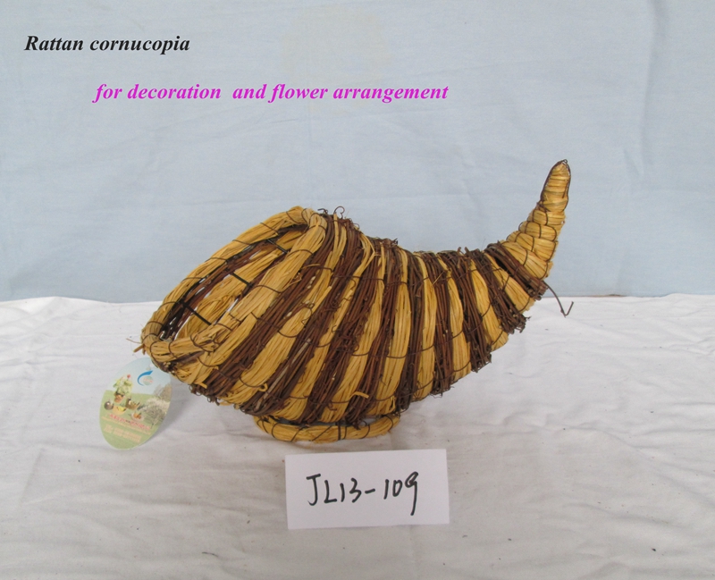
Weaving Basket :
Weaving basket are purely weaved by handmade
with the natural raw material, such as the bamboo chip, wood chip, sea
grass ,water hyacinth , awn and fern.
The main feature of the weaving basket is exquisite workmanship and
long durability.
For the exquisite workmanship,it can be used as Christmas Basket and festival decoration.
For the long durability, it can be used as Storage Basket and laundry
basket.
Size and shape description: We have our own factory and design department ,we can do any size and shape according to
customer's demand.
If you have any interest with our products, please feel freely to
contact with us. All our Jinliang staffs sincerely welcome you visit our
factory and office. For inquiry, please send mail directly to us.
Weaving Basket,Weaving Cornucopia,Weaving Handicraft,Plastic Weave Basket Guangxi Pubei Jinliang Arts and Crafts Co.,ltd , https://www.arts-manufacturers.com