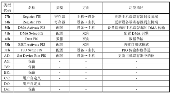
In the previous articles, we have analyzed the physical layer and link layer of the SATA protocol. We will continue to analyze the transport layer of the SATA protocol. The function of the transport layer, in a nutshell, is to adapt the data format of the two-layer transmission to the application layer and the link layer. It starts the data packet transmission according to the read/write request command of the application layer and the response information of the link layer. The transport layer controls the format of the Frame Information Structures (FIS) for transmitting control commands and data between the host and the hard disk. The transport layer does not change the content of the transmitted data, and only the data to be transmitted to the application layer is packed into data frames. The structure and restore the received data frame to data transmission to the link layer. Specifically, the transport layer is mainly responsible for encapsulation and parsing of the FIS frame information structure. When transmitting data, the transport layer encapsulates the commands and data in the mapping register according to the protocol-defined structure, and then passes the encapsulated frame information structure to the link layer for transmission; when receiving data, the transport layer transmits the data transmitted by the link layer. The flow is parsed according to the corresponding data structure specified by the SATA protocol, and various control words in the FIS are checked to view the data transmission status. The transport layer is located on the upper layer of the data link layer and is mainly responsible for the encapsulation and decapsulation of the FIS (Frame Information Structure). It does not need to know how a frame of data is transmitted. It is only responsible for constructing FIS according to the upper layer command at the transmitting end, and extracting data and control information in the FIS at the receiving end. After the transport layer receives the upper FIS encapsulation request, the functions that need to be completed include: 1. Collect FIS content based on FIS request type; 2. Arrange FIS content in the order in which they are set; 3. Send a frame transmission request to the data link layer and send the FIS; 4. Manage the Buffer/FIFO data stream and inform the data link layer flow control when needed; 5. Receive a transmission status report of the other party from the data link layer; 6. Report the correct or incorrect transmission status to the upper layer; After the transport layer receives the FIS from the data link layer, the functions that need to be completed include: 1. Receive FIS and determine its type; 2. Assign FIS content to the specified location according to the type of FIS; 3. For the transport layer of the host side, when receiving the FIS, it also needs to return an FIS to the device end; 4. Report the correct or incorrect transmission status to the upper layer. After receiving the command request from the application layer, the transport layer encapsulates the information in the relevant register into FIS and transmits it to the data link layer according to the format specified by the SATA standard protocol. After the data link layer is successfully received, a status flag of the completion of the transmission is fed back to the transport layer. After receiving the FIS from the data link layer, the transport layer determines whether the FIS is valid and of type. If it is a valid type, it is parsed according to the format specified by the SATA standard protocol, and the data therein is mapped into the corresponding register, and then the application layer is notified to update the value of the corresponding register. If it is an invalid type, it is discarded. That is to say, the operation of the register is done at the transport layer. Table 1 shows the register list of SATA Table 1 SATA register list FIS (Frame Information Struction) is a set of DWs used for information exchange between the host and the device (including data and control information). It is combined with SOFP and EOFP as the start and end markers to form a complete one. Frame data. The SATA protocol defines eight FIS types, including register, configuration, and data. The first byte of the first DW of each FIS is the type code, which represents the type and name of the FIS. In addition, six sets of type values ​​are reserved for future version upgrades. Table 2 shows the type of FIS Table 2 Types of FIS for SATA Protocol Specifically introduce the function and structure of each FIS: The host register information frame, Register FIS - Host to Device, is used to pass the updated value in the host side register group to the device side register group. The FIS can only be sent by the host. Whenever the value of the host-side register group changes, the host can initiate a Register FIS - Host to Device to the device, and the device will update the parsed information to its own ATA register group and perform the corresponding operation. Register FIS - Host to Device has a type code of 27h, located at the first byte of the first DW. The FIS has a total of 5 DWs. The value of the C bit ("0" or "1") depends on the Command Register or the Device Control Register in the host register group. The Feature Register and the Device Register. (Device Register), LBA Address Register, etc. are obtained from the corresponding host-side register set. The R bit and the reserved byte are uniformly assigned "0". The frame structure is as follows: Figure 1 Register FIS - Host to Device frame structure When the contents of the command register or control register on the host side are changed, the host immediately triggers the contents of the map register to be sent out in the FIS structure package defined earlier. When the device end receives a host register information frame, the host side proposes a frame information command according to the structure defined by the protocol, controls the information, updates the corresponding information in the own map register, and determines whether to execute the command operation or perform the control operation. As can be seen from Figure 1, the frame consists of 5 groups of DWs, consisting of 20 bytes, containing information about the necessary registers. Device information frame, Register FIS - Device to Host is used to pass the updated value in the device side register group to the host side register group to feedback the command execution. The FIS can only be sent by the device. Whenever the device completes a command, the device will initiate a Register FIS - Device to Host to the host, and the host will receive and parse the information to update its own register set. Register FIS - Device to Host has a type code of 34h, located at the first byte of the first DW, which has 5 DWs. The I bit is the interrupt flag bit, the error register (Error Register), the status register (Status Register), the LBA address register, etc. are obtained from the corresponding device side register set, and the R bit and the reserved byte are uniformly assigned "0". The frame structure is shown in Figure 2: Figure 2 Register FIS - Device to Host frame structure When the device end needs to update the mapping register state of the host terminal after completing a certain command, the device register information frame is sent to the host end, and the command completion status and possible error information are reported to the host through the information of the status register. When the host receives a device register information frame, the host side parses the information frame according to the format specified by the protocol and updates the contents of the mapping register. The DMA response information frame, the DMA Activate FIS is used by the device to respond to the DMA transmission request initiated by the host, and the FIS can only be sent by the device. When the host needs to send multiple Data FISes to complete a DMA transfer process, the host must confirm that the DMA Activate FIS is successfully received before sending the Data FIS. This indicates that the device is ready to receive Data FIS. The type code of DMA Activate FIS is 39h, which is located at the first byte of the first DW. The FIS has a total of 1 DWs. The frame structure is shown in Figure 3: Figure 3 DMA Activate FIS frame structure The DMA establishes the information frame. When the DMA Setup FIS is used to access the host memory in the First-Party DMA mode on the device side, the host/device DMA controller is configured before the data is officially transferred. The FIS allows the device to establish a DMA channel by itself, and directly sends a request notification to the DMA controller, which can be sent by the host/device. The type code of the DMA Setup FIS is 41h, located at the first byte of the first DW, which has 7 DWs. Among them, the D bit represents the data transmission direction; the A bit indicates whether the first transmission of the Data FIS requires the DMA Activate FIS trigger; the I bit is the interrupt flag of the DMA transfer completion; the R bit and the reserved byte are uniformly assigned the value "0", and the frame structure thereof As shown in Figure 4: Figure 4 DMA Setup FIS frame structure Data information frame, Data FIS is used to transfer data between the host and the device, and the host/device can send. The Data FIS has a type code of 46h and is located at the first byte of the first DW. The length of the FIS is uncertain. According to the actual situation, the maximum value cannot exceed 2048 DWs. If the data to be sent is less than an integer multiple of DW, then "0" is required at the end of the data. The frame structure is as shown in Figure 5: Figure 5 Data FIS frame structure The BIST responds to the information frame. The BIST Activate FIS is used to enable the receiver to enter the loopback test mode, and the host/device can transmit. The type code of BIST Activate FIS is 58h, which is located at the first byte of the first DW. It does not appear during normal operation, and its frame structure is shown in Figure 6: Figure 6 BIST Activate FIS frame structure The PIO Setup establishes an information frame. The PIO Setup FIS is used by the device to provide sufficient information about the PIO data to the host, so that the host can control the PIO data transmission more effectively. The FIS can only be sent by the device. In the PIO transmission, whether the host sends data to the device or the device sends data to the host, the device sends a PIO Setup FIS to the host before each transmission of the Data FIS. The PIO Setup FIS has a type code of 5Fh and is located at the first byte of the first DW. The FIS has a total of 5 DWs. Among them, D bit represents the data transmission direction; I is the interrupt flag bit; R bit and reserved byte are uniformly assigned "0", and its frame structure is shown in Figure 7: Figure 7 PIO Setup FIS frame structure When the device needs to send or receive data, the device needs to send a PIO operation information frame to the host to notify the host of the PIO operation. Information, such as the address, sector size, status, etc. before and after PIO transmission. After the information frame is transmitted, the device enters the state of sending or receiving data and waits for the corresponding information of the host. The device sets the information frame. Set Device Bits FIS is used to update the register value of the host-side register group that only has write permission to the device, such as the error register and the 6 bits in the status register. The FIS can only be sent by the device. The device side first rewrites its own register, and then sends a Set Device Bits FIS to the host. When the host receives the rewritten content, it updates its own register. Set Device Bits The type code of FIS is A1h, which is located at the first byte of the first DW. The FIS has 2 DWs. Among them, Status Hi indicates the 4, 5, and 6 bits of the status register; Status Lo indicates the 0, 1, and 2 bits of the status register; I is the interrupt flag bit; R bit and reserved byte are uniformly assigned "0", and its frame structure is as follows Figure 8 shows: Figure 8 Set Device Bits FIS frame structure From the above analysis, it can be seen that the transport layer of SATA mainly processes information packets, and the registers used are similar to those of the PATA protocol. The next article will introduce the principle and structure of the application layer of SATA, so stay tuned. About Darth Technology Dasi Technology, a national high-tech enterprise, the only collaboration unit for the data recovery of the confidentiality of the Tianjin National Secrecy Bureau, a well-known brand in the data recovery and forensics industry, is a technology-based enterprise with technology research and development as its core productivity, at home and throughout Asia. Data recovery and forensics technology leading! Darth Technology China data recovery and forensics experts! More data recovery and forensics technology, Internet, please pay attention to WeChat public subscription number: woocs Micro signal: woocs Long press to identify the QR code Focus on data recovery and forensics technology, the Internet Submission:
Traffic signs are road facilities that use words or symbols to convey guidance, restriction, warning or indication information. In traffic signs, it is usually an important measure to implement traffic management and ensure road traffic safety and smoothness by setting eye-catching, clear and bright traffic signs.There are many types of traffic signs, which can be divided into main signs and auxiliary signs in various ways.Movable marks and fixed marks;Lighting signs, luminescent signs and reflective signs;And variable information signs that reflect the changing driving environment.
Road Sign Boards,Road Sign Traffic,Warning Traffic Sign,Aluminum Traffic Sign Chengdu GodShape Sign Co., Ltd , https://www.signsgs.com")
")
")
![]()
")
")
")
")
")
")